Dette er en gammel utgave av dokumentet!
Innholdsfortegnelse
Model-based engineering (BIM)
One of the advantages of designing with coordination models is more efficient design. Part of the planning can be done during the meeting process and provides a more direct process. Instead of creating traditional meeting minutes, corrections can be made in meetings by referring to places in the model with a direct inscription. To achieve this, the project must prepare routines for how participants in the project will deliver data, format of transfer files, responsible for deliveries of various subjects, time and deadline for deliveries to meetings.
The delivery includes basic models, subject models, coordination model and display model for all relevant subjects for the planning phase, with the necessary level of detail for the planning phase. It is pointed out that the delivery includes all interaction versions up to the finally accepted model.
The design should, unless otherwise agreed, build on any models that already exist from previous study and planning phases. Existing models are detailed and further enriched with information. The model includes both permanent facilities and temporary facilities to describe the implementation of the measure.
A project / assignment-specific strategy should be established for the use of models at the start of the project. The strategy should be adapted to the project's scope and should at least include specific objectives for model use in the project, a plan for tool use and possible training of project participants, role descriptions for model managers in the project, a plan for which types of models should be used in which meetings and contexts. plan for level of detail and data flow in the project. It must also, in consultation with the client, assess any need within each individual subject area for conventional drawings in addition to the models.
It must be taken into account that the model is also used as a basis for illustrations, visualizations, and that these are applied to map data, draped with a map basis, orthophoto, etc. If illustrations, visualizations or the like are prepared for public communication purposes, the designer is obliged to take the necessary precautions in descriptions of consequences for third parties.
The coordination model shows an updated collection of the professional models and basic data, with the correct placement of all elements and objects that have been projected at any given time.
Such an interdisciplinary coordination model has the advantages of:
- Greater understanding and respect for each other's subjects and limitations.
- Easier to identify conflict and problems that may arise during the implementation and construction of the facility. Visualizes area and volume requirements in the project, and possible conflict with the location of the objects, during the design phase. Reduces the need for changes and redesign during the construction phase.
- Higher quality and greater accuracy of what is projected. Designers must add more details and accuracy to the design so that the model looks as realistic as possible. Errors in the design are clear. A better design basis benefits the executing contractor who does not have to make adjustments on site. Ensure the possibility that the project is realistic and feasible.
- Form a common platform for interdisciplinary collaboration at design meetings
- Visibility requirements and the visual impression are simulated. Provides the opportunity for designers and possibly architects to design the facility in a visually best possible way for the travelers and to create a uniform and well-thought-out operating environment.
- The contractor receives more information that improves the calculation basis for pricing the assignment. Facilitates the ability to check data in the tender documentation and simulate the operation of the facility. More information creates greater trust between the client and the contractor and additions are prevented as a result of uncertainty and misunderstandings.
- Contractor gets more data for implementation and construction. Data from the model can be used directly on the construction site where all design data is available and easy to put out in the field.
- The model is the basis for increased documentation and control of the finished plant, and forms additional information in a final documentation.
- Provides an opportunity to make visible what the measure entails to the public, landowners and those who are to approve and adopt the plans.
How the result of such a collaboration model is to be used can vary from project to project, depending on the project's size, complexity, knowledge and form of contract.
A model only works when the latest updated data is included in the model. This means that the data flow in the project is important, regardless of who is designing or which programs are used for the design. The transmission of data must be coordinated in a readable format that ensures the quality and accuracy of the data. How this is to be implemented must be agreed in advance through contracts, agreements and guidelines.
3.4 Basic model
Basic models describe existing terrain and situation before the intended interventions have been carried out.
| Subjekt | Filename | General description | ||
|---|---|---|---|---|
| TERRAIN SURFACE | G_TERRENG_XX | Shows the current terrain with data from maps and supplementary measurements. Triangle model of the surface in the core area. The scope of supplementary measurements is clarified with the project manager for projects. All measurements must be coded in SOSI. | ||
| BASIC CONDITIONS IN THE GROUND | G_GRUNN_XX | Basic data (eg reports and maps). Base measurements and test drilling, depth of rock, seismic surveys and visual assessments. Applies to geology, loose materials and rocks. | ||
| EXISTING TRACKS | G_EKSSPOR_XX | Existing railway routes and station areas, as well as all existing railway objects. Measurements or data from Banedata | ||
| CONSTRUCTIONS | G_KON _XX | All relevant existing structures and underground facilities as a volume model, and should at least cover the entire construction area and 50-meter zone | ||
| GEOLOGICAL CONSTRUCTIONS | G_GEOKON_XX | Existing sheet piles and other geotechnical measures and geoconstructions. Columns, piles etc., lime stabilized areas, sheet piling and should at least cover the entire construction area and 50-meter zone | ||
| TUNNEL GEOLOGY | G_TUNNEL_GEO_XX | Interpreted parameters. Detailed rock forecast and detailed Rock Safety Classes I - VI. | ||
| WATER AND WASTEWATER | G_VA_XX | Obtained from the municipality's water and sewage department as well as any measurements. Also includes drainage and district heating. Handling of uncertainties at height is clarified with the project manager. | ||
| CABLES / ELECTRICITY / TELEPHONE / OTHER | G_KABEL_XX | All relevant existing cables. Obtained from cable owners as well as any measurements | ||
| OTHER EXISTING OBJECTS | G_EKSIST_XX | Retrieved primarily from FKB data and any measurements. In densely populated areas, details must be measured. The scope is clarified with project managers. In densely populated areas, it should be considered whether 3D volume of basement level in buildings should be modeled or measured. Existing buildings, noise barriers, planting, fences, station areas, roads and car parks, water | ||
| ADMINISTRATIVE BOUNDARIES AND SURFACES | G_PLAN_XX | Registered basic data on property boundaries etc. The basic data types «Thematic geodata» and «Documentation from previous project phases» form the basis for the model. | ||
| THEME (nature, cultural monuments, danger areas etc.) | G_TEMA_XX | Site-specific assessments. Reference is made to the Norwegian Public Roads Administration's handbook V712 Impact assessments, five main themes are mentioned for non-priced consequences: * Landscape image * Outdoor life / city and village life * Biodiversity * Cultural heritage * Natural resources The need for themes in models is clarified with the planning manager in the project. One must be aware of the quality of information in databases | ||
| EXTERNAL INTERFACES | G_XGRSN_XX | Interface with external actors or other Bane NOR projects. The need for your own model is clarified with the project manager. |
XX is free text, Free text can be lowercase letters
3.5 Professional models
Subject-specific design shall be defined separately as professional models. These should only show their own subject through specific objects and elements, and should not contain other elements or references to other subjects in the specific subject model. All subject models must use a common reference system and height so that all subject models can be entered directly into an overall model, coordination model without conversion or adjustments.
All subject models must be geographical models in plan / volume with a common reference system that can be used as input in the coordination model. Subject models are built up with all respective academic data with references to the object's or element's protrusion data. All data must have x, y and z coordinates in the given reference system.
| Subject | Filename | General description |
|---|---|---|
| TRASE | F_SPOR_XX | Track center tracks of new projected solutions Each track should have its own file with track number or track name. All necessary texts and mileage. |
| SUPERBUILDING | F_OB_XX | Shows construction of ballast, tracks and sleepers. Also applies to switches, joints, welds, etc. |
| UNDERBUILDING | F_UB_XX | Groundwork for substructure with marking of trough bottom, frost protection layer, slope deflection, cuts, formation plan shows the construction of substructure based on dimensioning basis. |
| COMMON ELECTRICAL | F_ELEKTRO_XX | Guideways, foundations, electrical engineering houses, cable glands. All cable ducts, pipe penetrations with troughs must be shown. Cable routing divided into low voltage and high voltage. External electrical systems if this is affected by the system. |
| TELE | F_TELE_XX | Telecommunication system. All internal and external cable routes with arrangements. External telecommunications systems if this is affected by the system. |
| LOW VOLTAGE | F_LSPENNING_XX | Low voltage systems. Lighting, group cabinets, and switch heating with cables and systems. |
| Catenary system | F_KL_XX | Catenary system. Masts, foundations, cables, bypass cables, switches, autotraph, suction transformer, spare current transformer, etc. |
| SIGNAL SYSTEM | F_SIGNAL_XX | Signaling system. All signals with cabling to rails, drive machines, safety systems and cabinets. Security line 150m.ing |
| CONSTRUCTIONS | F_KON_XX | All constructions and railway foundations in connection with the route. Constructions are delivered from the design consultant |
| TUNNEL | F_TUNNEL_XX | Tunnel profile and inner surfaces with bolts and securing equipment. Interior view with surface tunnel wall. |
| WATER AND WASTEWATER | F_VA_XX | External and internal pipelines, and troughs and gutters. Designed according to the municipality's Water and Sewerage norm and technical regulations |
| DRAINAGE | F_DREN_XX | All objects for drainage and other surface water treatment. |
| ROAD | F_VEG_XX | Everything in relation to the road. The free text field is used to distinguish e.g. signs, markings, lighting etc. |
| LANDSCAPE | F_LAND_XX | All subjects that lead to changes in terrain and surroundings. Noise barriers, planting, fences, ditch slopes, station areas and parking spaces. It is important to clarify the early boundary between the substructure, construction, road and landscape. This must be done in the building plan if not earlier. |
| MEASURES GEOLOGY, GEOTECHNIQUE AND HYDROGEOLOGY | F_GEO_XX | Measures lime / cement stabilization (KS) and any terrain rounding or other measures in and outside the railway facility such as. lots of replacements, light fills etc. A distinction must be made between temporary and permanent geotechnical structures |
| GEO CONSTRUCTIONS | F_GEOKON_XX | Terrain relief, backfilling, sheet piling and other support structures including stays, piles, lime / cement stabilization and other geotechnical measures, both temporary and permanent. A distinction must be made between temporary and permanent measures. |
| RAMS | RAMS-FARELOGG_XX | The naming of points in the model must correspond to the numbering in the hazard log and the RAM log. All site-specific points in the hazard log are registered as points in the model. The points can be as x and y. There are no requirements for z value beyond the projected elements in the subject models. If the visualization tool does not need the z-value, the advisor controls this himself. |
| SHA | F_SHA_XX | The naming of points in the model must correspond to the numbering in the hazard log. All site-specific points in the hazard log are registered as points in the model. The points can be as x and y. There are no requirements for z value beyond the projected elements in the subject models. If the visualization tool does not need the z-value, the advisor controls this himself. |
| PLAN | F_PLAN_XX | Limitation of the plan and any other necessary boundaries from the municipal sub-plan and zoning plan. Station buildings and technical buildings. Considering using Statsbygg's BIM manual. |
| ARCHITECTURE / BUILDINGS | F_ARK_XX | Station buildings and technical buildings. Considering using Statsbygg's BIM manual. |
| NOISE | F_STOY_XX | Noise code map with marking of red and yellow noise zone, or marking of noise load on buildings - then as red and yellow houses. |
| EXTERNAL INTERFACES | F_XGRSN_XX | Interface with external actors. Used if professional models are to be delivered to external actors. |
XX is free text
Each professional model must contain the projected system that is shown with surfaces and elements / objects based on the correct extent and location. The projected data in the subject model must be reproduced accurately and unadorned. Errors and omissions with objects must not be hidden or distorted but made visible in the model with warning or symbol.
What is projected shall be defined on the basis of a specific object type code list and structure of layers at all times to ensure the development of the digital data.
All subject models must be geographical models in plan / volume with a common reference system that can be used as input in the coordination model. Subject files are built up with all respective professional data with references to the object's or element's protrusion data. All data must have x, y and z coordinates in the given reference system. If it is to be projected in models, the objects and elements must also have a height reference.
The subject model must be kept up to date along the way, at agreed intervals. Common routines must be prepared for all participants in the design. When versions have been completed for consultation and approval, no changes must be made to professional models. The same applies to deliveries with the tender basis to contractors and building drawing audits.
If there has been a need to add guides or other files in the design, these must be removed before partial deliveries and when the drawing is announced as completed.
3.6 Coordination model
The coordination model is a model that brings together all professional models and basic models in one model through links. This forms the basis for looking at the total design regardless of who or which subject has designed or which tool has been used. It is suitable for regular review at design meetings, interdisciplinary controls, and a basis for defining the result model.
The coordination model is formed by putting together all basic models and professional models. It does not need to be drawn or edited in this model. All changes must be made to the subject models and re-generated to the coordination model.
The coordination model shall show the planned interdisciplinary situation in a given phase of the development. The model must be of such a nature that you can move around freely in the model. The model can be built up as a wire model or as a surface, or a combination of these. Subjects, teams or groups must be able to be switched on and off to be able to look under the overlying layers.
The format selected must be able to generate data from all the participating data models, without data being distorted or lost. The size and accuracy must be clarified with the client in advance based on data volumes and visualization tools.
The model is used for design purposes for interdisciplinary visual quality control in design. It can define visualized work tasks and phases during the construction period, and help ensure implementation. It can enhance the visual impression and design of the facility and contribute to an optimization of solutions. The model must be updated regularly, in accordance with updating of professional models, throughout the design phase. As a prerequisite for the project, intervals of 14 days should be set up, unless otherwise defined in the project.
An updated version of the subject model is regularly posted on the agreed catalog, and notification is sent as agreed to the coordinator in advance of design meetings, construction meetings, etc., so that the coordination model always shows the latest and current version at given times.
The coordination model can be the starting point for design meetings where a review of this forms the basis for meeting minutes and interdisciplinary coordination. The need for changes and updates that appear at a meeting is changed and corrected to the next meeting, or by appointment.
It is important that all deliveries in different subjects are coordinated so that an updated model can be reviewed at the agreed design meetings to get the full effect of the design.
Coordination models should be used for various purposes such as results, display, presentation or source model, arranged so that all the current subject models are copied into the model to be developed and all references are removed. The model will thus no longer be updated in the event of changes in the professional model
3.7 Model for construction, result model
As a description for construction, the profit model must be adapted as a tender basis and building documentation for the contractor. The model must contain all the elements and objects necessary to describe and build the plant. The model must be adapted for use in order to be able to extract stitching data or for use as machine control, if the contractor so wishes in the production phase. The model is also the basis for control during construction where volumes and location must be shown with any deviations.
The models must be designed so that they can be used for distribution on a tender basis. This applies to the coordination model and the separate subject models. The models must be able to be delivered in the production format and in open formats, and possibly a design format that is commonly used in the construction market.
Where the process is defined as calculated masses, the model shall be adapted to be able to calculate volumes in a model with possibilities for control calculation.
All elements and terrain lines must be clearly marked with points or reference lines.
The model must have good enough geometric accuracy to be able to be used as a basis for stitching and machine control during the construction phase without other additional information.
The result model shall provide access to geometry data and properties The model is delivered in a suitable format and agreed specifically with the client. The format must take care of the object's geometric design (volume / surfaces / lines / points) and properties. When the plant is completed, the model must be updated according to the actual situation. It is the measured data that will be the basis for the placement of objects and elements in the model.
The result models must be delivered with a stitching basis to the contractor. The objects must be delivered in such a way that they are suitable for the production of a stitching base where the reference point and lines are on the correct layer (prefix R). Objects with uniquely defined geometry are delivered as volumes or surfaces. Objects with assumed geometry must also be supplied with reference points / lines for sticking (eg point for center sump, line for bottom inner pipe).
3.8 Establishment of objects in models
All objects must be associated with the register of objects. In Bane NOR, this is BaneData's object registration system with a unique object ID. In a planning situation, these objects will be registered in BaneData with the status as PLANNED. When the plant is finished and ready for use, these will have the status IN OPERATION. Object ID is ordered / reserved either through established systems or by contacting Bane NOR.
In the event of changes to existing objects, the existing object ID must be used so that existing information and historical data about objects are continued. The choice of type of object must be made on the basis of requirements in technical regulations, RAMS specifications and experience.
The objects used should, as far as possible, be retrieved from Bane NOR's Object Library. If there are no correct objects in the library, it may be necessary to prepare this in the project. Such an object that is designed in the project goes to Bane NOR free of charge. The object is placed in into the correct place and height.
The objects must show the correct size, extent and appearance. It is important not to use objects that have too high a resolution, are too detailed, or require large digital capacity, as this will mean that the models become unnecessarily large and require a lot of data capacity.
In a design phase, product-specific objects or objects that through a distinctive appearance are not used until the choice of supplier has been chosen must be used.
3.8.1 Object library
Bane NOR has established a 3D object library which is under Supplier, requirements and security, Rules, routines, processes, circulars and applications, Digital planning at www.banenor.no. Object library Planners who work for Bane NOR are free to use the library for the design of railway facilities.
All objects must have the opportunity to be carriers of individual properties. The properties must include contribute to a consistent traceability from design, properties of production / supplier, location of object, and system for operation and maintenance. Especially components with great importance for safety and availability must be registered with production / supplier, location in the plant, and data that is important for operation and maintenance. This data is added as information associated with the model. The object properties are partly governed by guidelines in technical regulations, framework agreements, client-delivered material and deliveries given in tenders. The object properties are entered continuously in the model as these are made known. When the model is upgraded to the built level, all relevant object properties must be entered with a corrected location.
As a controlling parameter, all objects and elements that are included in the model are given in a specific structure.
3.9 Characteristics
Properties are additional information about the objects. There are currently no systems that link information to the object. How the information can be linked to the model will depend on software solutions. The requirement is that the defined content of data and transfer format is as defined.
Information can not normally be entered directly into the model. Normally, only one object type ID will be in the model.
All Objects entered in the subject model should have two layers:
- Layer 1 - The object marked as a symbol, with surfaces and volume. The team does not have a prefix.
- Layer 2 - Reference point or line of object. The insertion point is also the protrusion data for the object. The team is given with the prefix R- …… in front of the team name.
MODEL BUILDING
Properties
In addition to placing the design in the plane, a 3D model will define heights and form the basis for a three-dimensional visualized rendering of the plant. The design is more comprehensive but can have a number of advantages for larger and technically complicated plants.
- A common platform for all design. Creates greater understanding and respect for each other's subjects, and provides the basis for interaction and compromise solutions.
- Easier to detect conflicts and problems that may occur during construction and construction of the facility. Highlights the area and volume requirements of the project, and any collisions of objects, during the design phase. Reduces the need for changes and redesign during the construction phase.
- Higher quality and greater accuracy of what is being projected. Designers need to add more detail and accuracy to the design so that the model looks as realistic as possible. Errors in the design are evident. Better design basis is in favor of contractor who avoids making customizations on site.
- Visibility requirements and visual impressions are simulated. Provides the opportunity for design and possibly architects to design the facility in a visual way that is best for the traveler and to create a uniform and well thought out operating environment.
- The contractor receives more information that improves the calculation basis for the pricing of the contract. Facilitates the ability to check data in the tender documentation and simulate the operation of the plant. More information creates greater trust between the builder and the contractor and prevents additions as a result of uncertainty and misunderstandings.
- Contractor gets more data for completion and construction. Data from the model can be used directly at the construction site where all design data is available and easy to place in the field.
- The model is the basis for increased documentation and control of the finished plant, and provides additional information in a final documentation.
- Provides the opportunity to make visible what the measure entails to the public, the landowner and those who will approve and adopt the plans.
Data flow through the design
In order to achieve coordination between different subjects, several different consultants and with the use of several different software, the structure of the model must be structured according to a given structure. A common platform must be established with clear rules for communication and data transfer.
A common and coordinated basis for the design, basis data, must be established before the design starts. The data must be accessible and displayed without distortion or error for all participants. Changes to basic data during design must be notified and documented.
When designing, data must be made available and in a secure way. This applies both when using a project hotel or similar
In order for links and references in the model to be maintained, the latest updated models must retain the file name, while old outgoing elements may be renamed with, for example, prefix deleted.
BASIC DATA
Read in at the start of the project
- GEODATA: maps, lasers and measurements
- TECHNICAL DATA: Track data
- Water and drainage- CABLE DATA
PROJECTING
Updated regularly at design meetings until approval Level of detail depending on plan phase
- Modification and creation of elements, existing and new
- Define the measure approximately 1 to 1 format with all elements
- Displays the phases and order of the development measure
DATA RETURN Executed when the project is completed
- GEODATA, data is transferred to map owner
- TECHNICAL DATA affected data replace / input
- Water and drainage - CABLE DATA message for cable and water systems
Object Type ID
In order to be able to connect the model to external databases, and to give a good structure in the model, the model is built up with a standard object type ID. A list has been prepared that shows the structure and structure of the object types within the railway technical subjects.
The object type ID list o the object library is under construction and changes can occur without advance notice. For an overview of object type ID, see Object type list.
Object Library
In order to achieve efficient design of railway technology, the design is associated with the predefined railway technical objects. These are objects that may have been extracted from any previous project. Bane NOR has established a 3D object library under Supplier Information and Digital Planning at Bane NOR.no: Object Library
All objects should be able to bear individual properties. The properties should include: contribute to a continuous traceability from design, production / supplier characteristics, object placement, and operation and maintenance system. Particular components with great importance for safety and availability must be registered with the production / supplier, location in the plant, and data that are important for operation and maintenance. This data is entered as metadata into the model. The object properties are partly governed by guidelines in technical regulations, framework agreements, client-supplied materials and deliveries offered. The object properties are continuously added to the model as they are made known. When the model is upgraded to a built level, all relevant object properties must be entered with the correct location.
As the controlling parameter, all objects and elements included in the model are given in a specific structure, the process code. A library for object codes of standard railway technical elements is established.
It will be appropriate to find solutions to convert codes to other systems, such as to Rail Data, or process codes in the tender description, cost estimation tools, etc., to take advantage of the ability to automatically generate data.
Objects and Elements
All Objects entered in the subject model should have two layers:
Layer 1 - The object marked as symbol, with surfaces and volume. The layer does not have a prefix. Layer 2 - Reference point or line of object. The insertion point is also the protrusion data for the object. The layer is given with prefix R- …… in front of the layer name.
In the engineering of railway technology, and other purposes of 2D engineering, a number of symbols are used that illustrate objects of different kinds. In the project, standard symbol libraries for each subject will basically be used. If additional symbols are needed or these are not appropriate for any type of drawings, the project manager shall approve new symbols.
For 3D design, objects should show the correct size, extent and appearance. These objects can be retrieved from Bane NOR's object library. The choice of type of object must be made on the basis of requirements in the Technical Regulations, RAMS specifications and experience
If there is no correct object in the library, it may be necessary to prepare this in the project. Such an object that is prepared in the project accepts Bane NOR free of charge. The object is placed into the model with the correct location and height.
Metadata for objektet påføres ved innlegging av objektet. Om objektets ID er kjent så påføres dette. ObjektID blir generert fra Banedata. Det er normalt ikke generert ObjektID før i detalj eller byggeplanfasen. Om ikke ID er kjent påføres en midlertidig prosjektrelatert ID som senere kan skiftes ut når ObjektID er kjent. Figur 7.5: Objektet plasseres inn i modellen og påføres Objekt-ID.
Metadata
Metadata is additional data that normally cannot be entered directly into the model. Usually, only one object type ID will be in the model. How data can be associated with the model will depend on software solutions. The requirement is that the defined content of data and transmission format is as defined. An example is metadata:
- Path number (NNNN) (defined by default; the parcel path number in Path Data, possibly the project's defined parcel designation.)
- Track number <NN>
- Parcel <nn>
- Mileage
- Location in terrain coordinate based
- Object code <custom process code>
- Type description with e.g. type of drawing no.
- Object Properties <Documentation Proarc Reference>
- RAMS properties. Life Considerations
- Manufacturer's name, year of manufacture, component type / number,
- Reference to supplier info, identification, serial number etc.
- Maintenance instructions, operating instructions
- Date of admission
Subject Models
All subject models shall use a common reference system and height so that all subject models can be entered directly into a unified model, coordination model.
Everything that is projected should be defined from the default object type list for layer structure. This is to ensure that the different subject models can be incorporated into a common model.
Each subject model should be displayed with surfaces and elements / objects of real extent. The projected data in the subject model must be reproduced accurately and unmasked. Errors and defects in the stitching base should not be concealed.
All professional models must be available in agreed version of the DWG format, latest version of the SOSI (GML) format, LandXML, possibly KOF, and in a format defined by the client. The files must be in a defined reference system and all lines defined as sticking lines must contain geometry or crack lines.
Objects depend on the supplier and will not be described until the supplier is selected. The items should then only be displayed as an example without being specified with the product's brand or design. Object library should be neutral to supplier.
To the extent that the DAK program defines layers, layers in the 3D model must be defined according to object code list. All objects and elements are defined in two main types of layer structure; reference point (sticking data) and extent (area / volume). This is done to split reference points that define placement against other surfaces and volumes.
- Object TypeID
- Process Code O
- bject Code
- Description
- Autocad
- Images
- Specification
- 452247009
- 3.21.1111
- Steel mast B4, 8m
- steel mast_b4_80.dwg
- Center top foundation
Table 7.7: Example of object contact structure mast structure in the object library:
Coordination model
The coordination model is formed by putting together all basic models and subject models. It should not be drawn or edited in this model as this should only be a blank drawing with links and references to the other models and files. All changes must be made to the subject models and re-generated to the coordination model.
The coordination model should show planned interdisciplinary situation in the given phase of the development. The model should be of such a nature that you can move around freely in the model, not as a film recording. The model can be built up as a wire model or as a surface, or a combination of these. Layers must be able to turn on and off to see below layers.
The designer must define the format in which the coordination model is to be built. The format chosen must be able to generate data from all the contributing data models, without any data being distorted or lost. The size and accuracy must be clarified with the client in advance based on data quantities and visualization tools.
Coordination model
The coordination model is formed by putting together all basic models and subject models. It should not be drawn or edited in this model as this should only be a blank drawing with links and references to the other models and files. All changes must be made to the subject models and re-generated to the coordination model.
The coordination model should show planned interdisciplinary situation in the given phase of the development. The model should be of such a nature that you can move around freely in the model, not as a film recording. The model can be built up as a wire model or as a surface, or a combination of these. Layers must be able to turn on and off to see below layers.
The client must define the format in which the coordination model is to be built. The size and accuracy must be clarified with the client in advance based on data quantities and visualization tools.
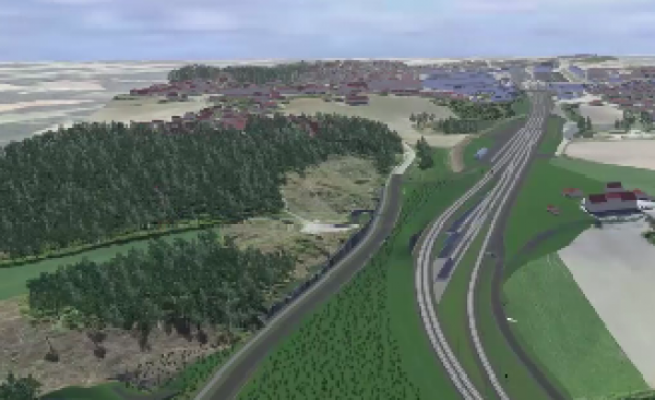
Figure 7.8 shows an example of a coordination model in which all subjects are entered.
The model is used for design purposes for multidisciplinary visual quality control in design. It can define visualized work tasks and phases during the construction period, and help ensure completion. It can enhance visual impressions and design of the facility and help optimize solutions.
Creating Drawings
A drawing can contain both schematics or floor plans.
A schematic drawing shows the functions and connections in the plant, everything from track plans to electric power plants. There are special subject-specific requirements for such schematic drawings, often with their own symbols, as shown in Symbolbibliotek.
A plane drawing can be considered as a model in the plane without heights. Drawings have been the traditional ones the way to project, in which requirements-specific subject-specific drawings are drawn up in plan, with tables and with schematics.
Methods for making geographical floor plans are largely similar to the process of making models.
Drawing Types
Drawings to be prepared will vary from project and design phase. The starting point is that all drawings are generated from the plan model so that the interfaces between the drawings are taken care of.
The result file is understood to be drawings composed of one or more theme files and / or other files (like xref). All result files must be taken from the same xrefs shown in coordination model.
The result file (s) should have file names that reflect the drawing number (s). The file name should only contain drawing number, not revision number. In the file format pdf of the drawing, this should contain revision number.
Layer Name Rules
The course code should be the first part of the name. Then the name must be categorized and detailed depending on subject and object type acc. the tables on the next pages. All “TEMA” must be referred to subjects Build layer names in theme files:
* TEMA_CATEGORY_DETAIL * _TEMA and _Category (as listed in the tables below) should not be changed.
If required, it can be supplemented by additional _Category. If more details are needed this is specified in each project.
Automatically generated layers should retain their names. This applies to objects created in accordance with NS3451 building part table and the like. Naming requirements only apply to teams that are manually named.
| TEMA | Description |
|---|---|
| JBT | Collection designation of railway technical layers in the drawing. |
| JBTEL | Railway low-voltage technical systems (NS 3451 (ELI) and NS 8351 are used where this is natural) |
| JBTEH | Railway technical high voltage systems (50Hz high voltage systems - not KL / rail current) |
| JBTJORD | Railway grounding systems |
| JBTKL | Contact line systems |
| JBTEF | Railway power supply plant |
| JBTOB | Superstructure |
| JBTTE | Telecommunications |
| JBTSI | Signal systems |
Table shows codes for naming themes in layer names
| JBTEL_EKS | Existing plant / object can be assigned $ EKS by subject name. Here's an example of low voltage |
| JBTEL_PROSJ | Displays a projected solution for telecommunications |
| JBTEL_ALT1 | Displays various options for telecommunications systems (here option 1) |
| JTOB_FASE10_SPV2_SSS | Displays phase 10 for a track switch 2 based on the stick rail joint. |
Table showing examples of using layer names